


LESSO

LESSO GROUP HOLDINGS LIMITED
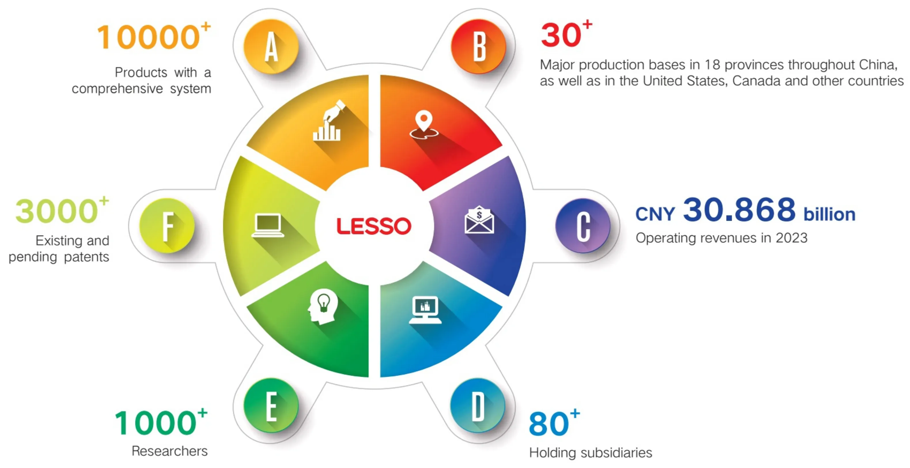
Established in 1986, LESSO (Stock Code: 02128.HK) is a global leader in home furnishings and building materials. The Group's business porflio spans plastic piping, building materials and home furnishings, environmental protection, new energy, supply-chain service platforms and others. It offers a wide range of products such as pipes, photovoltaics, plumbing and sanitary ware, integral kitchen materials, integral doors and windows,aluminum formwork and smart scaffolds,water purifiers, water-proofing materials and sealants, fire-fighting equipment, valves, cables, lighting, hygiene materials, items for environmental protection, agricultural facilties, and oceanic aquaculture cages.In 2023,LESSO's sales revenuereached overUSD 4.38billion.
Since implementing a strategy of globalization and expanding its global presence, LESSO has evolved into a sophisticated multinational. It boasts more than 30 advanced productionbases worldwide,broadening its industrial and sales networks to cover Asia, North America, South America,Europe,Africa,and Oceania.This enables LESSO to provide quality products and services for global customers in accordancewith its continuously improved strategic layout in a timely and efficient way.
LESSO has founded its R&D center with more than 1,000 scientific researchers, nationally accredited enterprise technology center, and two post-doctoral workstations to support its innovation and technical development. The Group has taken a leading role in the revision of over 120 international and Chinese industry standards. LESSO owns over 2,900 patents (some of them are pending), and provides over 10,000 varieties of products, making it one of the most comprehensive manufacturers in the piping industry. Its products are utlized globally in different areas, including home decoration, civil construction, municipal water supply, drainage, energy management, power supply and telecommunications, gas supply, fire-fighting, environmental protection, agriculture, oceanic aquaculture, etc.
True to its idea of “Envisioning the Better, Building the Future", LESSO remains committed to creating a better living environment, and advocating ideal cities featuring greenness, livability, and eficiency. With concerted efforts from various sectors, LESsO wil fully play its role in sustaining healthy and beautiful space so that global residents could enjoy a comfortable life.

With United Minds and Strengths, Gather Momentum for Better Advancement
China Lesso Group Holdings Limited (hereinafter referred to as LESSO,Stock Code: 2128.HK) is a global industrial group of building materials and home furnishings.Its business porfolio encompasses industrial sectors such as pipes, building materials and home furnishings, environmental protection, as well as channelsandservices.
Contents
Engineering Technical Manual for Plastic Inspection Chamber (Type I)
1.Introduction, Structure and Features of Plastic Inspection Chamber...... ..01 1. Introduction toPlastic Inspection Chamber 2. Structures and Features of Plastic Inspection Chambe
Il.SystemCompositionandNaming RulesforPlastic Inspection Chamber......
1.SystemComposition
2. Naming Rules for Chamber Body and Accessory Codes
Il.Specifications for Riser Socket and Branch Pipe SocketofChamberBody.... .04 1.Specificationsfor Riser Socket and Branch Pipe Socket of Chamber Body
IV.Selection and ConnectionInstructionsforRiserPipes..05 1.Type-based Selection and Connection Instructionsfor Riser Pipes
1.Typesof Common ConstructionBranchPipes
2.Specification-based Selection and Connection Instructionsfor Branch Pipes
3. Type-based Selection and Connection Instructions for Branch Pipes
VI. Naming Rules, Specifications, Types and Scope of ApplicationforSeal Rings... 14-17 1. Coding Rules for Seal Rings 2. Specifications,Types and Scope of Application for Seal Rings
Vl. Usage Instructions for Reducing Joint .. 18-21
1. Detailed Types of Reducing Joint I
2. Matched Seal Rings for Reducing Joint I
Vll.IntroductiontoFunctionsandConnectionMethodsfor CertainAccessoriesofInspectionChamber....22-24 1. Introduction to Functions and Connection Methods for Accessories
IX.ElevationofInspectionChamber. 25-26 1.ElevationofSiltSettling ChamberBody
2.Elevations of Launder Chamber Body,Chamber Cover and Convergent WallingCrib
X.Installation ofAccessories 27-29
1. Installation Instructions for Gutty Inlet
2. Installation Instructions for Outlet Pipe
3. Installation Instructions for Saddle Joint
Xl.Construction InstructionsforPlasticInspection Chamber .30-33
1. Transportation
2.Storage of Inspection Chamber
3.Preparations Before Construction
4.Technical Guidelines for Construction
I . Introduction, Structure and Features of Plastic Inspection Chamber
1. Introduction to Plastic Inspection Chamber
(1) Plastic inspection chamber for drainage: Featured by a modular structure, the plastic inspection chamber for drainage is usually composed of a chamber body, a riser, accessories and a chamber cover. It is used for connection, dredging and maintenance of buried drain pipes.
(2) Chamber body: It refers to the part at the bottom of the inspection chamber with an interface connected with the drain pipe.
(3) Riser: The ascending passage part that connects to the chamber body at the bottom.
(4) Pipe connection socket: It refers to the component of the inspection chamber that is used for collecting and discharging rainwater and sewage, and for connecting with the drain pipe.
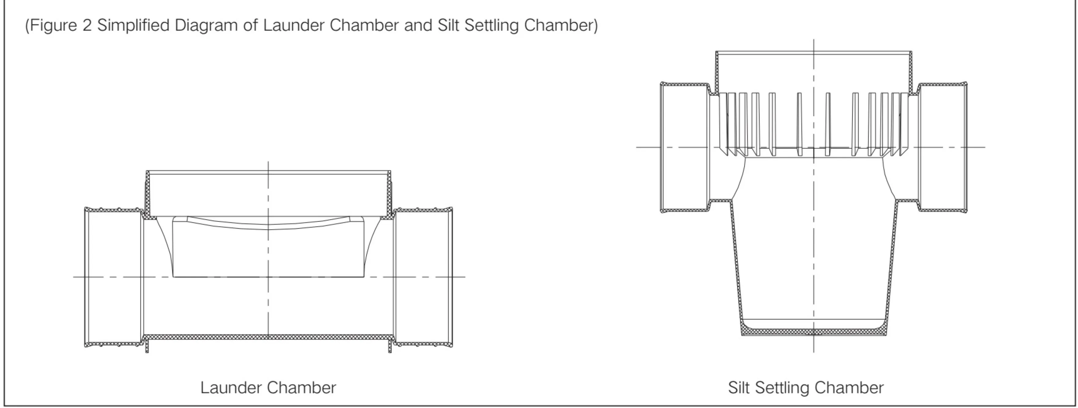
(5) Silt settling pit: It refers to the hopper-shaped chamber that is set up at the bottom of the inspection chamber for collecting impurities from the pipe.
(6) Launder: It is the semicircular sink connected to the upstream and downstream pipes at the bottom of the inspection chamber.It serves to guide the water flow and avoid eddy currents caused by cross-sectional changes in water flow, which could maintain a steady flow state and preventsludgeretention.
(7) Inspection ladder: It is the component that is used in the inspection chamber to allow installation and inspection personnel to climb up and down.
(8) Protective cover frame (bearing ring): The cover frame is installed on the concrete foundation around the riser to prevent the vehicle load from directly acting on the riser of the inspection chamber.
2. Structure and Features of Plastic Inspection Chamber
(1) The plastic inspection chamber is mainly composed of a chamber cover, riser, chamber body and accessories.
(2) The plastic inspection chamber is light in weight, and easy to install and transport.
(3)Processed by one-step injection molding,the plastic inspection chamber offers strong bearing capacity,excellent impact resistance, and smooth inner walls that prevent the retention of dirt and reduce the possibility of blockage, significantly improving the drainage efficiency.
(4) It is characterized by good corrosion resistance,excellent aging resistance and a long service life (the service life of the buried plastic inspection chamber is more than 5 times that of the brick inspection chamber).
(5) It canbeeasily connected with thepipe through theflexible connectionof thepipe and the chamber bodyto ensure uniform settlement, which effectively solves the uneven settlement caused by the connectionbetween the traditional brick inspection chamber and the pipe.With excellent airtightness, plastic inspection chambers effectively prevent sewage leakage,achieving safe and environmentally friendly effect.
(6) The riser can be cut, opened and adjusted on site to meet various installation depth requirements.
(7) Construction can be carried out 24h a day, which improves the construction progress and efectively reduces costs.The construction speed is over 10 to 20 times faster than that of traditional inspection chambers.


Il . System Composition and Naming Rules for Plastic Inspection Chamber
1. System Composition
The inspection chamber is composed of a chamber body, riser, chamber cover or protective cover frame and inspection chamber accessories.Asshowninthefigurebelow.

(1) The chamber body is divided into two types: launder chamber and silt settling chamber;
(2) Chamber covers usually include PVC-U chamber covers, cast iron inspection chamber covers, composite inspection chamber covers, and steel fiber reinforced concrete inspection chamber covers;
(3) Risers generally feature PVC-U hollow-wall riser pipes and HDPE spiral reinforced hollow-wall riser pipes.

| Corresponding CodesforDifferentProductTypes | ||||||||
| Codes | Product Types | No. Product Types | No. | Product Types | No. | Product Types | ||
| L | Launder Chamber1 | 01 | Initial Chamber Body1 | 31 | 45° Elbow | | 58 | Riser Converging Five-way Coupling1 | |
| N | Silt Settling Chamber l | 02 | Coupling Chamber Body1 | 32 | Convergent Walling Crib (Spigot)| | 59 | Coupling Chamber Body with Five Branch Pipes I | |
| F | Valve Chamberl | 03 | Reducing Coupling Chamber Body1 | 33 | Convergent Walling Crib (Socket)I | 60 | Tee ChamberBody with Five Branch Pipes 1 | |
| T | Communication Cable Chamberl | 04 | 15°Elbow Chamber Body1 | 34 Saddle Joint I | 61 | 90°Left Tee Chamber Body1 | ||
| Y | Oil Stain Isolation | 05 | 30°Elbow Chamber Body1 | 35 | Riser Coupling I | 62 | 90°Right Tee Chamber Body1 | |
| 06 | 45°Elbow Chamber Body| | 36 | Riser Straight Coupling I | 63 | Riser Plug | |||
| Chamberl | 07 | 90°Elbow Chamber Bodyl | 37 | Riser Converging Two-way Coupling I | 64 | Polymer Chamber Cover | ||
| P | Accessory SeriesI | 08 | 90°Tee Chamber Body1 | 38 | Riser Converging Teel | 65 | Polymer Chamber Cover (for Rainwater) | |
| S | WaterMeterChamber | 60 | 120°Tee Chamber Body| | 39 | Converging Reducing Joint I | 66 | PolymerChamberCover(forSewage) | |
| 10 | Y-shaped Tee Chamber Body I | 40 | Pavement Gutter InletI | 67 | Heat Shrinkable Belt 1 | |||
| 11 | 45° Left Lateral Tee Chamber Body1 | 41 | Lateral Gutter Inlet I | 68 | Composite Round Chamber Cover (for Sewage)1 | |||
| 12 | 45°Right Lateral Tee Chamber Body 1 | 42 | Extension Pipe I | 69 | Composite Round Chamber Cover (for Rain water) 1 | |||
| 13 | 90°Converging Tee Chamber Body1 | 43 | Fall-arrest Chamber Coverl | 70 | Composite Round Chamber CoverI | |||
| 14 | 90°Cross Chamber Body1 | 44 | Protective Coverl | 71 | VariableCornerJointI | |||
| 15 | 45°Lateral Cross Chamber Body1 | 45 | Square Chamber Coverl | 72 | Oil Stain Isolation Chamberl | |||
| 16 | Left Lateral Cross Chamber Body| | 46 | Heat Shrinkable Belt (for Riser and | 73 | Cable ChamberJointI | |||
| 17 | Right Lateral Cross Chamber Body| | Chamber Body Connection)1 | 74 | Cable ChamberCoverl | ||||
| 18 | Chamber Body with Muliple Access Branch Pipes 1 | 47 | Heat Shrinkable Belt(for Chamber | 75 | CleanoutI | |||
| 19 | Coupling Chamber Body with Two Branch Pipes 1 | Body and Branch Pipe Connection)I | 76 | Valve Chamber1 | ||||
| 20 | Coupling Chamber Body with Three Branch Pipes 1 | 48 | Round Lawn Chamber Cover I | 77 | Cleanout Chamber Cover| | |||
| 21 | Six-way Chamber Body1 | 49 | Adjustable Riser l | 78 | Oil Stain Isolated Chamber Semi-basket I | |||
| 22 | Adjustable Chamber| | 50 | Hole Tapper I | 79 | Lateral Gutter Inlet Lawn Chamber Cover1 | |||
| 23 Reducing Joint 1 | 51 | Riser Connectorl | 80 | Filter Mesh I | ||||
| 24 | Transition Adapter for Chamber Body (Socket) 1 | 52 | WaterGratel | 81 | Coupling Valve Chamber| | |||
| 25 | Kitchen &Bathroom Garbage Collector| | 53 | Square Lawn ChamberCoverl | 82 | Tee Valve Chamberl | |||
| 26 | Rainwater Garbage CollectionBasket1 | 54 | Movable Inspection Ladder I | 83 | Square | |||
| 27 Plug 1 | 55 | Fixed Inspection Ladder 1 | 84 | Composite Round Bearing Chamber Coverl | ||||
| 28 | Upper Antiextrusion Ring 1 | 56 | Cleanout ToolI | 85 | WaterMeter Chamber (Two-layer with | |||
| 29 | Lower Antiextrusion Ring 1 | 57 | Transition Adapter for ChamberBody | Chamber Cover) | ||||
| 30 | Chamber Casing 1 | (Spigot) 1 | ||||||
II. Specifications for Riser Socket and Branch Pipe Socket of Chamber Body
1. Specifications for Riser Socket and Branch Pipe Socket of Chamber Body
Figure 3: Chamber Body Diagram
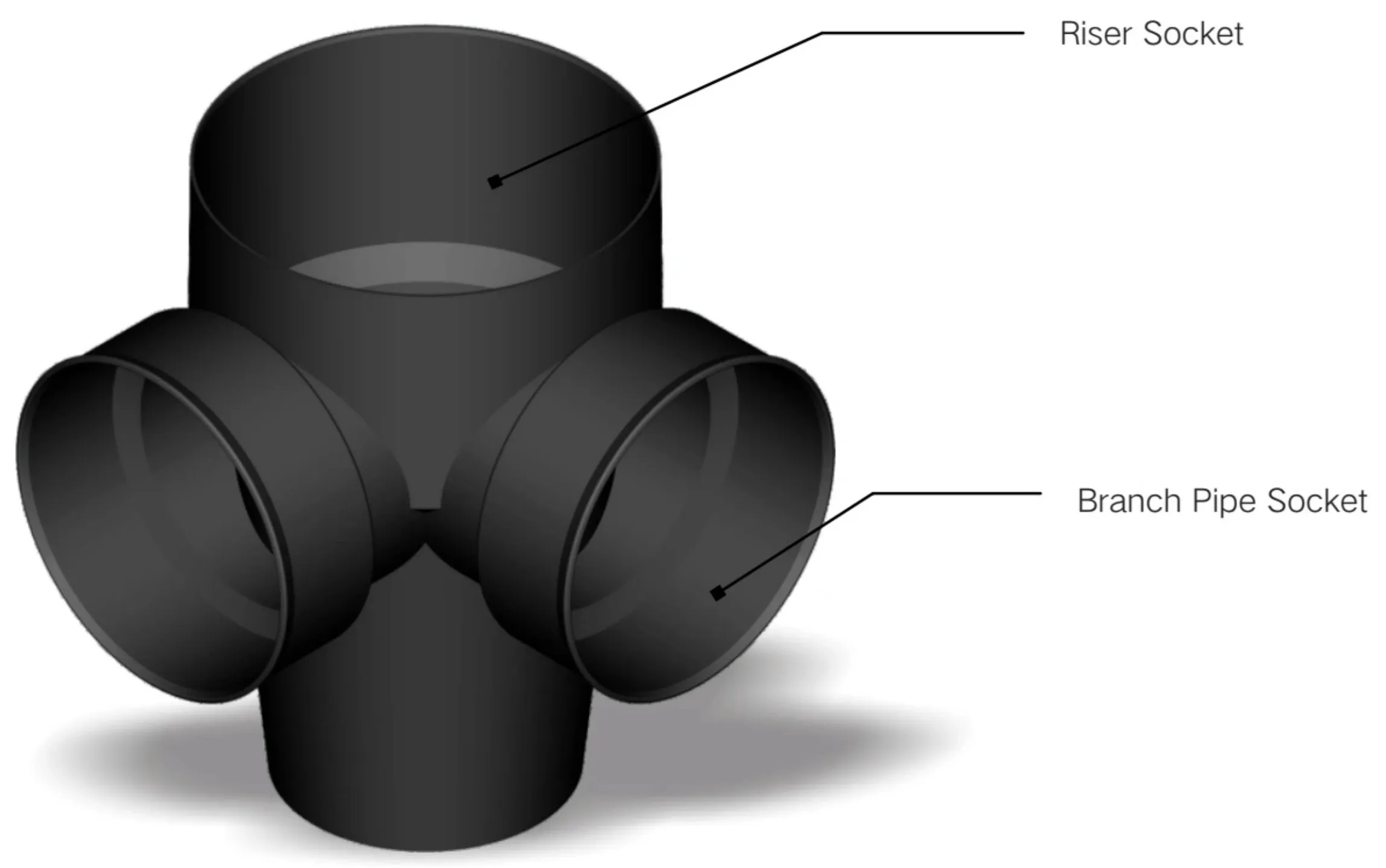
| Table 2:ReferenceTable for theSpecifications of RiserSocketand BranchPipeSocket | ||
| BranchPipeSocketSpecifications | RiserSocketSpecifications | |
| InnerDiameter | OuterDiameter | |
| 200A | 110B | DN200 |
| 225A | 160B | DN315 |
| 300A | 200B | DN400 |
| 400A | 250B | DN450 |
| 500A | 315B | DN500 |
| 600A | 400B | DN600 |
| 700A | 500B | DN630 |
| 800A | 600B | DN700 |
| 1000A | DN800 | |
| DN1000 | ||
| DN1200 | ||
IV. Selection and Connection Instructions for Riser Pipes
1. Type-Based Selection and Connection Instructions for Riser Pipes

| No. | Riser PipeTypes | Nominal Diameters | Matched Riser Socketsfor ofRiserPipe InspectionChamber | ConnectionMethodsbetween Pipeand BranchPipeSocket | RiserSeal Ring Specifications | HeatShrinkable BeltSpecifications | |
| 1 | HDPE Reinforced Hollow-Wall Riser Pipe I | DN315 | 315 | Seal Ring Connection or Heat Shrinkable Belt Connection | LS01-3151 | P146-325x100(315) | |
| 2 | PVC-U Spiral Hollow-Wali Pipe I | DN315 | 315 | Seal Ring Connection or Heat Shrinkable Belt Connection | LS01-3151l | P146-325x100(315) | |
| 3 | HDPE Reinforced Hollow-Wall Riser Pipe I PVC-U Spiral Hollow-Wall Pipe I | DN400 | 400 | Seal Ring Connection or Heat ShrinkableBelt Connection | LS01-400 | P146-421x100(400) | |
| 4 | DN450 | 450 | Seal Ring Connection or Heat Shrinkable Belt Connection | LS01-450 | P146-465x200(450) | ||
| 5 | DN500 | 500 | Seal Ring Connection or Heat Shrinkable Belt Connection | LS01-500 | P146-526x100(500) | ||
| 6 | DN600 | 600 | Seal Ring Connection or Heat Shrinkable Belt Connection | LS01-600/630 | P146-623x100(600) | ||
| 7 | DN630 | 630 | Seal Ring Connection or Heat ShrinkableBeltConnection | LS01-600/630 | P146-650x100(630) | ||
| 8 | DN700 | 700 | Seal Ring Connection or Heat ShrinkableBelt Connection | LS01-700 | P146-717×150(700) | ||
| 9 | DN800 | 800 | Seal Ring Connection or Heat ShrinkableBeltConnection | LS01-800 | P146-820x150(800) | ||
| 10 | HDPE Reinforced Hollow-Wall Riser Pipe I | DN1000 | 1000 | Seal Ring Connection or Heat Shrinkable Belt Connection | LS01-1000 | P146-995×150(1000) | |
| 11 | DN1200 | 1200 | Heat Shrinkable Belt Connection | P146-1300×300(1200) | |||
V. Selection and Connection Instructions for Branch Pipes
1. Types of Common Construction Branch Pipes
(1) Types and specifications of branch pipes are shown in Table 4:

| No. | Name ofBranchPipes | Nominal DiameterofBranchPipes |
| 1 | PVC-UWaterPipe | 110、160、200、250、315、400、500、630 |
| 2 | PVC-U Drain Pipe | 110、160、200、250、315、400、500、630 |
| 3 | PVC-MWaterPipe | 110、160、200、250、315、400、500、630 |
| 4 | PEWaterPipe | 110、160、200、250、315、400、500、630、710、800、1000 |
| 5 | Trenchless PESolid-Wall Pipe (for Drainage) | 110、160、200、225、250、315、355、400、450、500、630、710、800 |
| 6 | PVC-U Double-Wall Corrugated Pipe (GB Outer Diameter) | 110、160、200、250、315、400、500、630、800、1000 |
| 7 | HDPE Double-Wall Corrugated Pipe (GB Outer Diameter) | 110、160 |
| 8 | HDPEDouble-Wall Corrugated Pipe (N-shaped Pipe) | 225、300、400、500、600 |
| 9 | HDPEDouble-Wall Corrugated Pipe (GB Inner Diameter) | 200、225、300、400、500、600、700、800 |
| 10 | PE Spiral Structured-Wall Pipe Type A | 200、250、300、350、400、450、500、600、700、800、900、1000 |
| 11 | Metal Reinforced PESpiral Corrugated Pipe | 200、300、400、500、600、700、800、900、1000 |
| 12 | ElectricFusion Soft ManagementSet | 200、300、400、500、600、700、800、900、1000 |
2. Specification-based Selection and Connection Instructions for Branch Pipes
| Branch Pipe Diameter | BranchPipeTypes | Connection Methods | Seal Ring Specifications | HeatShrinkable Belt Specifications |
| 110B | PVC-UWaterPipe | Flexible Seal Ring Connection | LS07-110BBranchPipeSeal Ringl | |
| PVC-U Drain Pipe | FlexibleSeal Ring Connection | LS07-110B BranchPipeSeal Ringl | ||
| PVC-MWaterPipe | Flexible Seal Ring Connection | LS07-110BBranchPipeSeal Ringl | ||
| PEWaterPipe | Flexible Seal Ring Connection | LS07-110B Branch Pipe Seal Ring1 | ||
| TrenchlessPESolid-wallPipe (for Drainage) | Flexible Seal Ring Connection | LS07-110B Branch Pipe Seal Ring 1 | ||
| PVC-U Double-wall Corrugated Pipe (GB Outer Diameter) | Flexible Seal Ring Connection | LS03-110BPVC-UDouble-wall | ||
| HDPEDouble-wallCorrugated Pipe(GBOuterDiameter) | Flexible Seal Ring Connection | CorrugatedPipe RubberSeal RingI LS02-110B HDPE Double-wall Corrugated PipeStraightPipe RubberSeal RingI | ||
| 160B | PVC-UWaterPipe | Flexible Seal Ring Connection | LS07-160B Branch PipeSeal Ring I | |
| PVC-U Drain Pipe | Flexible Seal Ring Connection | LS07-160BBranchPipeSeal Ringl | ||
| PVC-MWaterPipe | Flexible Seal Ring Connection | LS07-160B Branch Pipe Seal RingI | ||
| PEWaterPipe | Flexible Seal Ring Connection | LS07-160B Branch Pipe Seal Ringl | ||
| Trenchless PE Solid-wall Pipe (for Drainage) | Flexible Seal Ring Connection | LS07-160BBranchPipeSeal Ringl | ||
| PVC-UDouble-wallCorrugated | LS03-160B PVC-U Double-wall | |||
| Pipe (GB Outer Diameter) HDPE Double-wallCorrugated | FlexibleSeal Ring Connection | CorrugatedPipe RubberSeal Ringl LS02-160BHDPEDouble-wallCorrugated | ||
| 200A | Pipe(GB Outer Diameter) HDPE Double-wall Corrugated | Flexible Seal Ring Connection FlexibleSeal Ring Connection or | Pipe Straight Pipe Rubber Seal Ringl LS02-N200-SN4, LS02-N200-SN8 HDPE Double-wall | P147-248×200 (200A) |
| Pipe (N-shaped Pipe) PESpiral Structured-wall PipeType A PE Spiral Structured-wallPipe TypeB | HeatShrinkableBeltConnection HeatShrinkableBeltConnection | CorrugatedPipeStraightPipeRubberSeal Ringl | P147-248×200 (200A) | |
| 200B | (Soft Management Set) PPVC-UWaterPipe | for A-to-D Reducing Joint FlexibleSeal Ring Connectionor | P147-218×200 (200B) 10 P147-215x150 (200B) | |
| PVC-U Drain Pipe | HeatShrinkableBelt Connection FlexibleSeal Ring Connection or | LS05-200B Reducing Joint Seal Ring I | ||
| PVC-MWaterPipe | HeatShrinkable Belt Connection FlexibleSeal Ring Connection or | LS05-200B Reducing Joint Seal Ring I | ||
| PEWaterPipe | HeatShrinkableBeltConnection FlexibleSeal RingConnectionor | LS05-200B Reducing JointSeal Ring1 LS05-200BReducingJointSeal Ringl | ||
| TrenchlessPESolid-wall Pipe | HeatShrinkableBelt Connection FlexibleSeal Ring Connection or | LS05-200B Reducing Joint Seal Ring1 | ||
| (for Drainage) PVC-U Double-wallCorrugated | HeatShrinkable Belt Connection FlexibleSeal Ring Connection or | LS03-200BPVC-UDouble-wallCorrugated | ||
| Pipe (GB Outer Diameter) | HeatShrinkableBeltConnection | Pipe Rubber Seal Ring1 | ||
| 225A | HDPE Double-wall Corrugated Pipe (N-shaped Pipe) | FlexibleSeal Ring Connection or HeatShrinkableBeltConnection | LS02-N225HDPEDouble-wallCorrugated Pipe Straight Pipe Rubber Seal Ringl | P147-275×200 (225A) |
| HDPE Double-wall Corrugated Pipe | FlexibleSeal Ring Connectionor HeatShrinkableBelt Connection | LS02-225A HDPE Double-wallCorrugated PipeStraightPipe RubberSeal Ringl |
| Branch Pipe Diameter | BranchPipe Types | Connection Methods | Seal Ring Specifications | HeatShrinkable BeltSpecifications |
| 250B | PVC-UWaterPipe | FlexibleSeal Ring Connection or Heat Shrinkable Belt Connection | LS05-250B/225A ReducingJointSeal Ring1 | P147-265x200 (250B) |
| PVC-U DrainPipe | FlexibleSealRingConnectionor HeatShrinkableBeltConnection | LS05-250B/225A Reducing JointSeal Ringl | ||
| PVC-MWaterPipe | FlexibleSeal Ring Connectionor HeatShrinkable Belt Connection | LS05-250B/225AReducingJointSealRingl | ||
| PE Water Pipe | FlexibleSeal Ring Connectionor HeatShrinkableBeltConnection | LS05-250B/225A ReducingJointSeal Ring1 | ||
| TrenchlessPESolid-wallPipe (for Drainage) | FlexibleSeal Ring Connectionor HeatShrinkableBeltConnection | LS05-250B/225AReducingJointSealRing1 | ||
| PVC-U Double-wall Corrugated Pipe (GB Outer Diameter) | Flexible Seal Ring Connectionor HeatShrinkableBeltConnection | LS03-250B PVC-U Double-wall CorrugatedPipeRubberSeal Ringl | ||
| 300A | LS02-N300-SN4,LS02-N300-SN8 | P147-375x200 (300A) | ||
| HDPE Double-wall Corrugated Pipe (N-shaped Pipe) | FlexibleSeal Ring Connectionor Heat Shrinkable Belt Connection | HDPE Double-wall Corrugated Pipe StraightPipeRubberSeal Ringl | ||
| HDPE Double-wall Corrugated Pipe | FlexibleSeal Ring Connection or HeatShrinkable Belt Connection | LS02-300AHDPEDouble-wallCorrugated PipeStraightPipe RubberSeal RingI | ||
| PESpiral Structured-wallPipeType A PE Spiral Structured-wallPipeTypeB (Soft Management Set) | Heat Shrinkable Belt Connection for A-to-D Reducing Joint | |||
| MetalReinforcedPE Spiral CorrugatedPipe | HeatShrinkableBeltConnection for A-to-DReducing Joint | |||
| 315B | Flexible Seal Ring Connectionor | P147-340×200(315B) | ||
| PVC-UWaterPipe | HeatShrinkableBelt Connection FlexibleSeal RingConnectionor | LS01-315 1 Riser Seal Ring l | ||
| PVC-UDrainPipe | Heat Shrinkable Belt Connection | LS01-3151RiserSeal Ring1 | ||
| PVC-MWaterPipe | FlexibleSeal Ring Connectionor HeatShrinkableBeltConnection | LS01-3151RiserSeal Ring1 | ||
| PEWaterPipe | FlexibleSealRingConnectionor HeatShrinkableBeltConnection | LS01-3151RiserSeal Ring1 | ||
| TrenchlessPESolid-wallPipe (for Drainage) | FlexibleSeal Ring Connectionor HeatShrinkableBeltConnection | LS01-3151 RiserSeal Ring1 | ||
| PVC-UDouble-wallCorrugated Pipe(GBOuterDiameter) | FlexibleSeal Ring Connectionor HeatShrinkableBeltConnection | LS03-315BPVC-UDouble-wall Corrugated PipeRubberSeal Ringl | ||
| 400A | HDPE Double-wall Corrugated Pipe (N-shaped Pipe) | Flexible Seal Ring Connectionor HeatShrinkableBeltConnection | LS02-N400-SN4,LS02-N400-SN8 HDPE Double-wall Corrugated Pipe StraightPipe RubberSeal Ringl | P147-505×200(400A) |
| HDPE Double-wall Corrugated Pipe (GB Inner Diameter) | FlexibleSeal Ring Connection or HeatShrinkableBeltConnection | LS02-400AHDPEDouble-wallCorrugated Pipe Straight Pipe RubberSeal RingI | ||
| PE Spiral Structured-wall PipeType A PE Spiral Structured-wallPipe Type B (Soft Management Set) | HeatShrinkableBeltConnection for A-to-D Reducing Joint | |||
| Metal Reinforced PE | HeatShrinkable Belt Connection | |||
| Spiral Corrugated Pipe | for A-to-D Reducing Joint |
| Branch Pipe Diameter | BranchPipeTypes | ConnectionMethods | Seal RingSpecifications | HeatShrinkable BeltSpecifications |
| PVC-UWaterPipe | FlexibleSeal Ring Connection or HeatShrinkableBeltConnection | LS05-400B Reducing Joint Seal Ring I | P147-428×200(400B) | |
| PVC-U Drain Pipe | Flexible Seal Ring Connection or HeatShrinkableBelt Connection | LS05-400B Reducing Joint Seal Ring l | ||
| PVC-MWaterPipe | FlexibleSeal Ring Connection or HeatShrinkable Belt Connection | LS05-400B Reducing Joint Seal Ring l | 10 P147-428×300(400B) | |
| 400B PEWaterPipe | FlexibleSeal Ring Connectionor HeatShrinkableBeltConnection | LS05-400BReducing JointSeal Ring1 | ||
| TrenchlessPESolid-wallPipe (for Drainage) | FlexibleSeal RingConnectionor HeatShrinkableBelt Connection | LS05-400B Reducing Joint Seal Ring l | ||
| PVC-U Double-wall Corrugated Pipe (GB Outer Diameter) | FlexibleSeal Ring Connection or HeatShrinkableBeltConnection | LS03-400BPVC-U Double-wall Corrugated Pipe RubberSeal RingI | ||
| 500A | HDPE Double-wall Corrugated Pipe (GB Inner Diameter) | FlexibleSeal Ring Connectionor HeatShrinkableBeltConnection | LS02-500A HDPE Double-wall Corrugated PipeStraightPipe RubberSeal RingI | P147-605×200(500A) 10 P147-605×250(500A) 10 P147-605×300(500A) or P147-605×400(500A |
| PESpiral Structured-wallPipeType A PESpiral Structured-wallPipeTypeB (SoftManagementSet) | HeatShrinkableBeltConnection forA-to-DReducing Joint | |||
| Metal ReinforcedPE Spiral CorrugatedPipe | HeatShrinkableBelt Connection | |||
| HDPE Double-wall Corrugated Pipe (N-shaped Pipe) | for A-to-D Reducing Joint FlexibleSeal Ring Connection or HeatShrinkableBeltConnection | LS02-N500-SN4,LS02-N500-SN8 HDPEDouble-wall CorrugatedPipe | ||
| 500B | FlexibleSeal Ring Connectionor | StraightPipe Rubber Seal RingI | P147-527×250(500B) | |
| PVC-UWaterPipe | HeatShrinkableBelt Connection FlexibleSeal Ring Connection or | LS05-500BReducingJointSeal RingI | ||
| PVC-U DrainPipe | HeatShrinkableBelt Connection | LS05-500BReducingJointSeal Ring1 | ||
| PVC-MWaterPipe | FlexibleSeal Ring Connection or HeatShrinkableBelt Connection | LS05-500B Reducing Joint Seal Ring l | ||
| PEWaterPipe TrenchlessPESolid-wallPipe | FlexibleSeal RingConnectionor HeatShrinkableBeltConnection | LS05-500B Reducing Joint Seal Ring l | ||
| (for Drainage) PVC-U Double-wall Corrugated | FlexibleSeal Ring Connectionor HeatShrinkableBeltConnection FlexibleSeal Ring Connectionor | LS05-500BReducing JointSeal Ring1 LS03-500BPVC-U Double-wall | ||
| Pipe (GB OuterDiameter) HDPE Double-wall Corrugated Pipe(GB Inner Diameter) | HeatShrinkableBeltConnection FlexibleSeal Ring Connectionor | CorrugatedPipe RubberSeal Ringl LS02-600A HDPE Double-wall Corrugated | P147-720×250(600A) or P147-720×300(600A) or P147-720×400(600A) | |
| 600A | PE Spiral Structured-wall PipeType A PESpiral Structured-wallPipeTypeB | HeatShrinkableBelt Connection HeatShrinkableBeltConnection | PipeStraightPipeRubberSeal RingI | |
| (Soft Management Set) Metal Reinforced PE | for A-to-D Reducing Joint HeatShrinkableBelt Connection | |||
| Spiral Corrugated Pipe | for A-to-D Reducing Joint | LS02-N600-SN4,LS02-N600-SN8 | ||
| HDPE Double-wallCorrugated Pipe (N-shaped Pipe) | FlexibleSeal Ring Connectionor HeatShrinkableBeltConnection | HDPE Double-wallCorrugated Pipe Straight Pipe Rubber Seal Ringl | ||
| Branch Pipe Diameter | BranchPipeTypes | Connection Methods | Seal Ring Specifications | Heat Shrinkable BeltSpecifications |
| HDPE Double-wallCorrugated Pipe (GB Inner Diameter) | FlexibleSeal Ring Connection or Heat Shrinkable Belt Connection | LS02-700A HDPE Double-wall Corrugated Pipe Straight Pipe Rubber Seal Ringl | Custom | |
| 700A | PESpiral Structured-wallPipeType A PE Spiral Structured-wall PipeType B (Soft Management Set) | HeatShrinkableBeltConnection for A-to-D Reducing Joint | ||
| Metal ReinforcedPE | HeatShrinkable Belt Connection | |||
| 800A | Spiral CorrugatedPipe | for A-to-D Reducing Joint | P147-1005×250(800A) 10 P147-1005×400(800A) | |
| HDPEDouble-wall Corrugated Pipe (GB Inner Diameter) | FlexibleSeal Ring Connectionor HeatShrinkableBeltConnection | LSO2-800A HDPEDouble-wall Corrugated Pipe StraightPipe RubberSeal Ringl | 10 P147-1005×450(800A) 10 P147-1005×500(800A) or P147-1005×600(800A) 10 P147-840×400(800A) | |
| PESpiral Structured-wallPipeType A PESpiral Structured-wallPipeType B (Soft Management Set) | HeatShrinkableBeltConnection for A-to-D Reducing Joint | |||
| Metal Reinforced PE Spiral Corrugated Pipe | HeatShrinkableBeltConnection for A-to-D Reducing Joint | |||
| PE Spiral Structured-wall PipeType A PESpiral Structured-wallPipeTypeB (Soft Management Set) | HeatShrinkable Belt Connection for A-to-D Reducing Joint | P147-1100×400(1000A) or P147-1100×450(1000A) or P147-1100×500(1000A) | ||
| 1000A | Metal Reinforced PE Spiral Corrugated Pipe | HeatShrinkableBelt Connection for A-to-D Reducing Joint | 10 P147-1153×300(1000A) or P147-1153×450(1000A) or P147-1153×500(1000A) |
| No. | Typesof BranchPipes | Nominal Diameterof BranchPipes | Types of Branch Pipe Socketsfor Inspection Chambers | Connection Methods | Seal Ring Specifications | Heat Shrinkable BeltSpecifications |
| PVC-U WaterPipe, PVC-U Drain Pipe, PVC-M Water Pipe, PE Water Pipe, Trenchless PE Solid-wallPipe | DN110 | 110B | Seal Ring Connection | LS07-110BBranchPipeSeal Ringl | ||
| DN160 | 160B | Seal Ring Connection | LS07-160BBranchPipeSeal Ring1 | |||
| DN200 | 200B | Seal Ring Connection or Heat ShrinkableBelt Connection | LS05-200BReducingJointSealRing1 | P147-218×200 (200B) | ||
| DN250 | 250B | Seal Ring Connection or Heat ShrinkableBeltConnection | LS05-250B/225AReducingJointSealRingl | P147-265×200 (250B) P147-340×100 (315B) | ||
| DN315 | 315B | Seal Ring Connection or Heat ShrinkableBeltConnection | LS01-3151RiserSeal RingI | or P147-340×200(315B) | ||
| DN400 | 400B | SealRingConnectionorHeat Shrinkable Belt Connection | LS05-400B Reducing Joint Seal Ring1 | P147-428×300 (400B) P147-428×200 (400B) | ||
| DN500 | 500B | Seal RingConnectionorHeat Shrinkable Belt Connection | LS05-500BReducingJointSeal Ringl | P147-527×250 (500B) | ||
| 2 | PVC-U Double-wall Corrugated Pipe (GB Outer Diameter) | DN110 | 110B | Seal Ring Connection | LS03-110B PVC-U Double-wall CorrugatedPipe RubberSeal Ringl | |
| DN160 | 160B | Seal Ring Connection | LS03-160BPVC-U Double-wall CorrugatedPipeRubberSeal RingI | |||
| DN200 | 200B | Seal Ring Connection or Heat Shrinkable Belt Connection | LS03-200B PVC-U Double-wall Corrugated Pipe RubberSeal RingI | P147-215×150 (200B) or P147-218×200 (200B) | ||
| DN250 | 250B | Seal Ring Connection or Heat Shrinkable Belt Connection | LS03-250B PVC-U Double-wall Corrugated Pipe Rubber Seal Ring I | P147-265×200 (250B) | ||
| DN315 | 315B | Seal Ring Connection or Heat ShrinkableBeltConnection | LS03-315BPVC-UDouble-wall Corrugated Pipe Rubber Seal Ringl | P147-340×100(315B) or P147-340×200(315B) | ||
| DN400 | 400B | Seal Ring Connection or Heat Shrinkable Belt Connection | LS03-400B PVC-U Double-wall Corrugated Pipe RubberSeal RingI | P147-428×300(400B) or | ||
| DN500 | 500B | Seal Ring Connectionor Heat | LS03-500BPVC-UDouble-wall | P147-428×200 (400B) P147-527×250 (500B) | ||
| 3 | ShrinkableBeltConnection | CorrugatedPipeRubberSeal Ringl | P147-248×200 (200A) | |||
| DN200-SN4 | 200A | Seal Ring Connection or Heat Shrinkable Belt Connection | LS02-N200-SN4 HDPE Double-wall Corrugated Pipe Straight Pipe Rubber Seal Ring I | |||
| HDPE Double-wall Corrugated Pipe (N-shaped Pipe) | DN200-SN8 | 200A | Seal Ring Connection or Heat Shrinkable Belt Connection | LS02-N200-SN8 HDPE Double-wall Corrugated Pipe Straight Pipe Rubber Seal RingI | P147-275×200 (225A) | |
| DN225 | 225A | Seal Ring Connection or Heat Shrinkable Belt Connection | LS02-N225 HDPE Double-wall Corrugated PipeStraightPipeRubberSeal RingI | |||
| DN300-SN4 | 300A | Seal Ring Connection or Heat Shrinkable Belt Connection | LS02-N300-SN4 HDPE Double-wall Corrugated PipeStraightPipeRubberSeal RingI | P147-375×200 (300A) or P147-375×300 (300A) | ||
| DN300-SN8 | 300A | Seal Ring Connection or Heat ShrinkableBelt Connection | LS02-N300-SN8HDPEDouble-wallCorrugated Pipe Straight Pipe Rubber Seal RingI | |||
| DN400-SN4 | 400A | Seal Ring Connection or Heat Shrinkable Belt Connection | LS02-N400-SN4 HDPE Double-wallCorrugated PipeStraightPipeRubberSeal RingI | P147-505×200(400A) or P147-505×250 (400A) | ||
| DN400-SN8 | 400A | Seal Ring Connection or Heat Shrinkable Belt Connection | LS02-N400-SN8 HDPE Double-wall Corrugated PipeStraightPipeRubberSeal RingI | or P147-505×300 (400A) |
| Table6Type-basedSelectionand ConnectionInstructionsforBranchPipes | ||||||
| No. | Typesof BranchPipes | Nominal Diameterof BranchPipes | Typesof Branch Pipe Socketsfor Inspection Chambers | ConnectionMethods | Seal Ring Specifications | HeatShrinkable BeltSpecifications |
| HDPE Double-wall Corrugated Pipe (GB Outer Diameter) | DN110 | 110B | Seal Ring Connection or Heat Shrinkable Belt Connection | LS02-110BHDPEDouble-wallCorrugated PipeStraightPipeRubberSeal Ringl | ||
| DN160 | 160B | Seal Ring Connection or Heat Shrinkable Belt Connection | LS02-160B HDPE Double-wall Corrugated Pipe Straight Pipe Rubber Seal Ringl | |||
| DN225 DN300 | 225A | Seal Ring Connection or Heat Shrinkable Belt Connection | LS02-225AHDPEDouble-wallCorrugated Pipe Straight Pipe Rubber Seal RingI | P147-275×200 (225A) | ||
| 5 | 300A | Seal Ring Connection or Heat Shrinkable Belt Connection | LS02-300A HDPEDouble-wallCorrugated PipeStraightPipe RubberSeal RingI | P147-375×200(300A) 10 P147-375×300 (300A) | ||
| DN400 | 400A | Seal Ring Connection or Heat ShrinkableBelt Connection | LS02-400A HDPE Double-wall Corrugated PipeStraightPipe RubberSeal Ring1 | P147-505×200 (400A) or P147-505×250 (400A) J0 | ||
| DN500 | 500A | Seal Ring Connection or Heat ShrinkableBelt Connection | LS02-500A HDPE Double-wall Corrugated PipeStraightPipe RubberSeal RingI | P147-505×300 (400A) P147-605×200 (500A) or P147-605×250 (500A) J0 | ||
| HDPE Double-wall Corrugated Pipe (GBInnerDiameter) | P147-605x300 (500A) J0 P147-605×400(500A) P147-720×250 (600A) | |||||
| DN600 | 600A | Seal Ring Connection or Heat Shrinkable Belt Connection | LS02-600A HDPE Double-wall Corrugated PipeStraightPipe RubberSeal RingI | or P147-720x300 (600A) or P147-720×400 (600A) | ||
| DN700 DN800 | 800A | 700A | Seal Ring Connection or Heat Shrinkable Belt Connection Seal Ring Connection or Heat Shrinkable Belt Connection | LS02-700A HDPE Double-wall Corrugated Pipe Straight Pipe RubberSeal RingI LS02-800A HDPE Double-wallCorrugated Pipe Straight Pipe RubberSeal Ring I | P146-820×150 (800) P147-1005×250 (800A) 10 P147-1005×400 (800A) J0 P147-1005×450 (800A) 10 P147-1005×500 (800A) 10 P147-1005×600 (800A) 10 P147-840×400 (800A) | |
| Nominal Diameterof BranchPipes | Typesof Branch Pipe Socketsfor Inspection Chambers | ConnectionMethods | Seal Ring Specifications | HeatShrinkable BeltSpecifications | ||
| No. | Types of BranchPipes | |||||
| 6 | 1. PE Spiral Structured-wall Pipe Type A 2. PE Spiral Structured-wall Pipe Type B (Soft Management Set) 3. Metal Reinforced PE Spiral Corrugated Pipe | DN200 | 200A | Heat Shrinkable Belt Connection for A-to-D Reducing Joint | P147-248×200 (200A) | |
| Dn300 | 300A | HeatShrinkable Belt Connection for A-to-D Reducing Joint | P147-375×200 (300A) or P147-375×300(300A) | |||
| Dn400 | 400A | Heat Shrinkable Belt Connection for A-to-D Reducing Joint | P147-505×200 (400A) or P147-505×250 (400A) P147-505x300 (400A) or | |||
| DN500 | 500A | HeatShrinkable Belt Connection for A-to-D Reducing Joint | P147-605×200 (500A) or P147-605×250 (500A) or P147-605×300 (500A) or P147-605×400 (500A) | |||
| DN600 | 600A | Heat Shrinkable Belt Connection for A-to-D Reducing Joint | P147-720×250 (600A) or P147-720×300 (600A) or | |||
| DN700 | 700A | HeatShrinkableBeltConnection for A-to-D Reducing Joint | P147-720×400 (600A) P147-840×400 (700A) | |||
| DN800 | 800A | HeatShrinkableBeltConnection for A-to-D Reducing Joint | P147-1005×250(800A) or P147-1005x400 (800A) or P147-1005×450 (800A) or P147-1005×500 (800A) or P147-1005×600(800A) or | |||
| DN1000 | 1000A | Heat Shrinkable Belt Connection for A-to-D Reducing Joint | P147-840×400 (800A) P147-1100×400 (1000A) P147-1100×450 (1000A) or or P147-1100×500 (1000A) or P147-1153×300 (1000A) or P147-1153×450 (1000A) or P147-1153×500(1000A) | |||
Vl. Naming Rules, Specifications, Types and Scope of Application for Seal Rings
1. Coding Rules for Seal Rings

| Table7TypesandCodeReferenceTableforSealRings | ||
| No. | Types ofSeal Rings | CodesofSeal Rings |
| 1 | RiserSeal Ringl | 01 |
| 2 | HDPEDouble-wall CorrugatedPipeStraightPipeRubberSeal RingI | 02 |
| 3 | PVC-UDouble-wallCorrugatedPipeRubberSealRingl | 03 |
| 4 | ConvergingJointSeal RingI | 04 |
| 5 | ReducingJointSealRingI | 05 |
| 6 | SaddleJointSeal Ringl | 06 |
| 7 | BranchPipeSeal Ringl | 07 |
| 8 | CommunicationChamberSealRingI | 08 |
| 9 | SocketSealRingIforElectricFusionSoftManagementSet | 09 |
| Name | Specifications | ScopeofApplication |
| RiserSeal RingI | LS01-3151 | 1.It is used for the connectionbetween the315Breducing joint and the315Bsocket of the inspectionchamber branch pipe. 2. It is used to connect the OD 315mm flat-wall pipe to the 315B socket and the saddle joint I of the inspection chamber branch pipe. |
| LS01-315I | It isused to connect theDN315HDPEspiralenhanced hollow-wall riserpipe andPVC-U hollow-wallriser pipe to the chamber body. | |
| LS01-400 | It is used toconnect theDN4o0HDPEspiral enhanced hollow-wall riserpipe andPVC-U hollow-wall riser pipeto thechamberbody. | |
| LS01-450 | It is used toconnect theDN450 HDPEspiral enhanced hollow-wall riserpipeandPVC-U hollow-wall riser pipe to the chamber body. | |
| LS01-500 | It is used toconnect theDN5oo HDPEspiral enhanced hollow-wall riserpipeandPVC-U hollow-wall riser pipe to the chamber body. | |
| LS01-600 | It isused to connectDN600 andDN630HDPEspiralenhancedhollow-wall riserpipesand thePVC-U hollow-wall riserpipe to thechamberbody. | |
| LS01-7001 | It is used toconnect theDN7o0HDPEspiral enhanced hollow-wall riserpipeandPVC-U hollow-wall riser pipe to the chamberbody. | |
| LS01-700 II | It isused toconnect theDN7ooHDPEspiral enhancedhollow-wall riserpipe andPVC-Uhollow-wall riserpipeto the chamberbody,and should be used inconjunctionwith thelower antiextrusion ring and thefall-arrest chamber. | |
| LS01-800 | 1. t is used to connect the DN8oo HDPE spiral enhanced hollow-wallriser pipe to the chamber body. 2. It is used for the connectionbetween the 7ooA reducing joint and the 7ooA socket of the branch pipe for an inspection chamber. | |
| LS01-800I | It isused toconnect theDN7ooHDPEspiral enhancedhollow-wall riserpipeandPVC-Uhollow-wallriserpipe tothe chamberbody,and should beused inconjunction with the lower antiextrusion ring and thefall-arrest chamber cover. | |
| LS01-1000 | 1.lt is used to connect the DN1ooo HDPE spiral enhanced hollow-wallriser pipe to the chamber body. 2. It is used for the connectionbetween the 8ooA reducing joint and the 8ooA socket of the branch pipe for an | |
| LS01-1000ll | inspection chamber. It isused toconnect theriserand theinternal plug-inclosureport tothechamberbody. | |
| HDPE Double-wall CorrugatedPipe Straight Pipe Rubber Seal Ringl | LS02-110B | socketof the inspectionchamberbranchpipe. |
| LS02-160B | ItisusedfortheconnectionbetweentheOD160mmHDPEdouble-wallcorrugatedpipeand the160B socketof theinspectionchamberbranchpipe. | |
| LS02-N200-SN4 | ItisusedfortheconnectionbetweenNseriesDN200SN4HDPEdouble-wallcorrugatedpipeand the200A socketof the inspectionchamberbranchpipe. | |
| LS02-N200-SN8 | socket of theinspection chamberbranchpipe. | |
| LS02-225A | Itisusedfortheconnectionbetween theDN225HDPEdouble-wallcorrugatedpipeand the225Asocket of the inspection chamberbranchpipe. | |
| LS02-N225 | ItisusedfortheconnectionbetweenNseriesDN225HDPEdouble-wallcorrugatedpipe and the225A socketof theinspectionchamberbranchpipe. | |
| LS02-300A | It isusedfortheconnectionbetween theDN300HDPEdouble-wallcorrugatedpipe and the300Asocket of theinspectionchamberbranchpiper. | |
| LS02-N300-SN4 | ItisusedfortheconnectionbetweenNseriesDN30ommSN4HDPEdouble-wallcorrugatedpipeand the 300Asocketof theinspectionchamberbranchpipe. | |
| LS02-N300-SN8 | ItisusedfortheconnectionbetweenNseriesDN300SN8HDPEdouble-wallcorrugatedpipeand the300A socket of the inspection chamber branch pipe. |
| Name | Specifications | ScopeofApplication |
| HDPE Double-wall Corrugated Pipe StraightPipe Rubber Seal Ringl | LS02-400A | It isusedfor the connectionbetween theDN400HDPEdouble-wall corrugatedpipe and the400Asocket of the inspectionchamberbranch pipe. |
| LS02-N400-SN4 | It isusedfortheconnectionbetweenNseriesDN400SN4HDPEdouble-wallcorrugatedpipeand the400A socketoftheinspectionchamberbranchpipe. | |
| LS02-N400-SN8 | It is used forthe connectionbetweenNseriesDN400SN8HDPEdouble-wallcorrugatedpipeand the 400A socketoftheinspectionchamberbranchpipe. | |
| LS02-500A | It isusedfortheconnectionbetween theDN5ooHDPEdouble-wallcorrugatedpipeand the5ooAsocketof theinspectionchamberbranchpipe | |
| LS02-N500-SN4 | It isusedfortheconnectionbetweenNseriesDN500SN4HDPEdouble-wallcorrugatedpipe and the500A socketoftheinspectionchamberbranchpipe. | |
| LS02-N500-SN8 | It is used forthe connectionbetweenN series Φ500mmSN8HDPEdouble-wall corrugatedpipe and the500A socket of theinspection chamberbranchpipe. | |
| LS02-600A | It isused fortheconnectionbetween theΦ600mmHDPEdouble-wall corrugatedpipe and the60oAsocket of the inspection chamberbranch pipe. | |
| LS02-N600-SN4 | It isusedfortheconnectionbetweenNseriesDN600SN4HDPEdouble-wall corrugatedpipe and the600A socketoftheinspectionchamberbranchpipe. | |
| LS02-N600-SN8 | It isused fortheconnectionbetween NseriesDN600SN8HDPEdouble-wall corrugatedpipe and the600A socketof theinspection chamberbranchpipe | |
| LS02-700A | It isused fortheconnectionbetween theDN7ooHDPEdouble-wallcorrugatedpipe and the7ooA socket of theinspectionchamberbranchpipe. | |
| LS02-800A | It isused fortheconnectionbetween theDN8o0HDPEdouble-wallcorrugatedpipeand the800Asocketof theinspectionchamberbranchpipe. | |
| PVC-U Double-wall Corrugated Pipe Rubber Seal Ringl | LS03-110B | It isusedfortheconnectionbetween theOD110mmPVC-U double-wallcorrugatedpipe and the110bsocket |
| LS03-160B | of theinspectionchamberbranchpipe It is usedfortheconnectionbetween theOD160mmPVC-U double-wallcorrugatedpipe and the160Bsocket | |
| LS03-200B | of the inspectionchamberbranchpipe. It isusedfortheconnectionbetween theOD200mmPVC-Udouble-wallcorrugatedpipeand the2oobsocket | |
| LS03-250B | of theinspectionchamberbranchpipe. It isusedfortheconnectionbetweentheOD250mmPVC-Udouble-wallcorrugatedpipeand the250Bsocket | |
| LS03-315B | of theinspectionchamberbranchpipe. It is usedfortheconnectionbetweentheOD315mmPVC-Udouble-wallcorrugatedpipe and the315Bsocket | |
| LS03-400B | of theinspectionchamberbranchpipe It isusedfortheconnectionbetween theOD400mmPVC-U double-wallcorrugatedpipeand the400Bsocket | |
| LS03-500B | of the inspection chamberbranchpipe. | |
| of theinspectionchamberbranchpipe | ||
| Converging Joint Seal Ring I | LS04-200B | It isusedfortheconnectionbetweenthe2ooBconvergingjoint and the2ooBsocketof theinspectionchamber branch pipe. |
| LS04-250B | It isusedfortheconnectionbetween the25oBconvergingjoint and the250Bsocketof theinspectionchamber branchpipe | |
| Name | Specifications | ScopeofApplication |
| LS05-200A | 1. It is used for the connection between the 20oA reducing joint and the 2ooA socket of the inspection chamber branch pipe. 1.It isusedfortheconnectionbetween the2ooBreducingjoint and the20oBsocketof theinspectionchamber | |
| LS05-200B | branch pipe. 2. It is used for theconnection between the OD200mmflat-wall pipe and the 200Bsocket of the inspection chamber branch pipe. | |
| LS05-200D | It isusedfortheconnectionoftheID2oommpipe. | |
| Reducing Joint Seal RingI | LS05-250B/225A | 1.lt isusedfortheconnectionbetween the25oBreducingjoint and the25oBsocketof theinspectionchamberbranchpipe. 2.It isusedfortheconnectionbetweenthe225Areducingjointand the225Asocketof theinspection chamberbranchpipe. 3.It isusedfortheconnectionbetweentheOD250mmflat-wallpipeandthe250Bsocketof theinspectionchamberbranch pipe. |
| LS05-300A | 1.lt isusedfortheconnectionbetweenthe30oAreducingjoint andthe3ooAsocketof theinspectionchamberbranchpipe. 2. It is used for the connection between the300A 45°elbow and the 300A socket of the inspection chamber branch pipe. | |
| LS05-300D | It isusedfortheconnectionoftheID3oommpipe. | |
| LS05-400A | 1.Itisusedfor theconnection between the 40oA reducing joint and the 400A socket of the inspection chamber branch pipe. 2. it is used for the connection between the 40oA 45°elbow and the 400A socket of the inspection chamber branch pipe. | |
| LS05-400B | 1. It is used for the connection between the 40oB reducing joint and the 4ooN socket of the inspection chamber branch pipe. 2. it is used for the connection between the OD 400mm flat-wall pipe and the 400Bsocket of the inspection chamber branch pipe. | |
| LS05-500A | 1.lt isused fortheconnectionbetween the5ooAreducingjoint and the5ooAsocketof theinspectionchamberbranchpipe. 2. It isused for the connectionbetween the5ooA45°elbow and the50oA socket of the inspectionchamberbranchpipe. | |
| LS05-500B | 1.lt is used fortheconnectionbetween the5ooBreducingjoint and the5ooBsocketof theinspectionchamberbranchpipe. 2.It is used for the connection between the OD5oomm flat-wall pipe and the 5ooB socket of the inspection chamber branch pipe. | |
| LS05-600A | 1.lt isusedfortheconnectionbetweenthe60oAreducingjoint andthe6ooAsocketof theinspectionchamberbranchpipe. 2. It isused for the connectionbetween the600A 45°elbow and the600A socket of the inspection chamber branchpipe. | |
| LS05-1000A | It is used for the connection between the 1oooA reducing joint and the 1oooA socket of the inspection chamber branch pipe. | |
| BranchPipe Seal Ring I | LS07-75B | It is used for the connection between the OD 75mm flat-wall pipe and the 75B socket of the inspection chamber branch pipe. |
| LS07-110B | It is used for the connection between the OD 110mm flat-wall pipe and the 110B socket of the inspection chamber branch pipe. | |
| LS07-160B | It is used for the connection between the OD 160mm flat-wall pipe and the 160B socket of the inspection chamber branch pipe. | |
| LS07-150A(160B) | It is used for the connection between the 160mm flat-wall pipe and the 150A socket of the inspection chamber branch pipe. |
Vll. Usage Instructions for Reducing Joint I
1. Detailed Types of Reducing Joint I
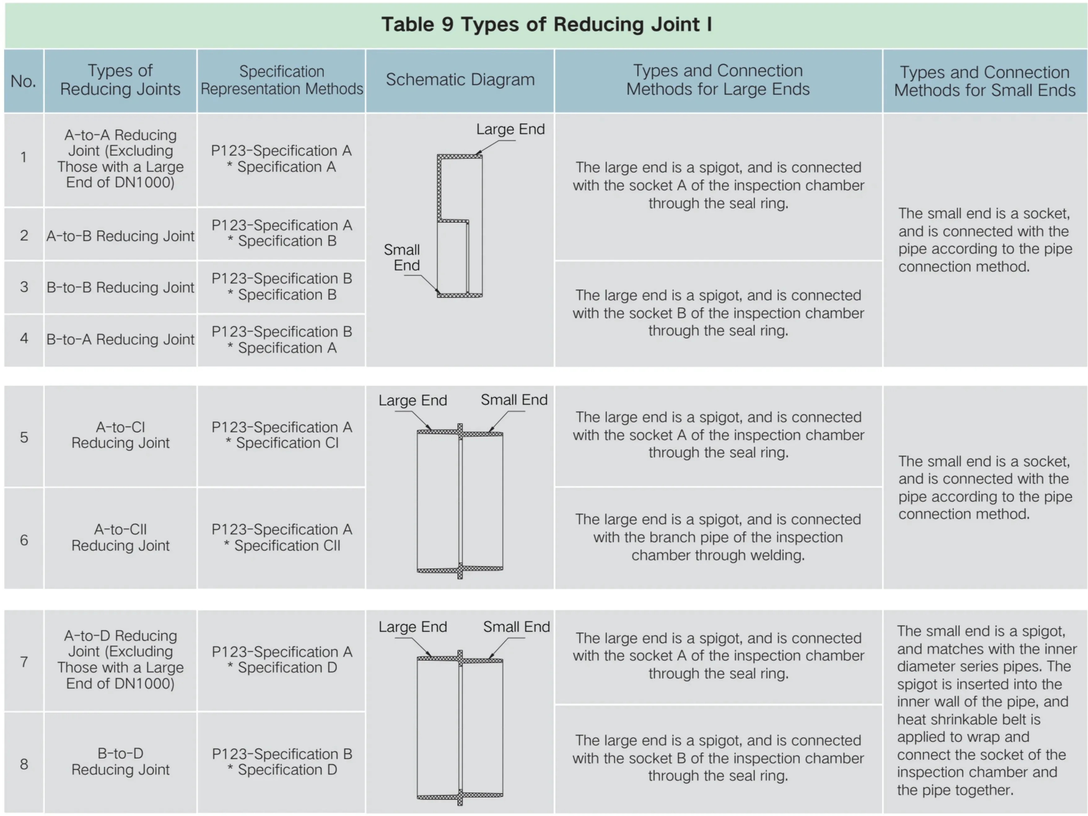
2. Matched Seal Ring for Reducing Joint I
| No. | SpecificationsofReducingJointl | SpecificationsofMatched Seal Ring for Reducing JointI | Remarks |
| 1 | P123-300A×300CII | No seal ring is required. | |
| 2 | P123-400A×400CII | No seal ring is required. | |
| 3 | P123-500A×500CII | No seal ring is required. | |
| 4 | P123-600Ax600CII | No seal ring is required. | |
| 5 | P123-1000Ax600A | LS05-1000 reducing joint seal ring I is optionally available. | |
| 6 | P123-1000Ax700A | LS05-1000 reducing joint seal ringI is optionally available. | |
| 7 | P123-1000Ax800A | LS05-1000 reducing joint seal ringI is optionally available. | |
| 8 | P123-1000Ax1000D | LS05-1000 reducing joint seal ring I is optionally available. | |
| 6 | P123-1000Ax1100D | LS05-1000 reducing joint seal ring I is optionally available. | |
| 10 | P123-1000Ax1200D | LS05-1000 reducing joint seal ringI is optionally available. | |
| 11 | P123-200B×200D | No seal ring is required. | |
| 12 | P123-315Bx300D | No seal ring is required. | |
| 13 | P123-400B×400D | No seal ring is required. | |
| 14 | P123-500Bx500D | No seal ring is required. | |
| 15 | P123-200Ax110B | LS05-200A Reducing Joint Seal Ringl | |
| 16 | P123-200Ax150A | LS05-200A Reducing Joint Seal Ringl | |
| 17 | P123-200Ax160B | LS05-200A Reducing Joint Seal Ringl | |
| 18 | P123-200Ax200B | LS05-200A Reducing Joint Seal Ring I | |
| 19 | P123-200A×200D | LS05-200A reducing joint seal ring 1 LS05-200B reducing joint seal ring 1 | Optional LS05-200Dreducing joint seal ring1 |
| 20 | P123-225A×150A | LS05-250B/225A Reducing Joint Seal Ring1 | |
| 21 | P123-225Ax160B | LS05-250B/225A Reducing Joint Seal Ring 1 | |
| 22 | P123-225Ax200A | LS05-250B/225A Reducing Joint Seal Ring1 | |
| 23 | P123-225A×200B | LS05-250B/225A ReducingJointSeal Ring1 | |
| 24 | P123-225A×250B | LS05-250B/225A Reducing Joint Seal Ring1 | |
| 25 | P123-300A×200A | LS05-300A Reducing Joint Seal Ring l | |
| 26 | P123-300Ax200B | LS05-300A Reducing Joint Seal Ring l | |
| 27 | P123-300A×225A | LS05-300A Reducing JointSeal Ringl | |
| 28 | P123-300A×250B | LS05-300A Reducing Joint Seal Ring I | |
| 29 | P123-300Ax300CI | LS05-300A Reducing Joint Seal Ringl | |
| 30 | P123-300Ax300D | LS05-300A reducing joint seal ring 1 LS05-300D reducing joint seal ringl | |
| 31 | P123-300Ax315B | LS05-300A reducing joint seal ring 1 | |
| 32 | P123-400A×200A | LS05-400A reducing joint seal ring 1 | |
| 33 | P123-400A×200B | LS05-400A reducing joint seal ring 1 | |
| 34 | P123-400A×225A | LS05-400A reducing joint seal ring 1 | |
| 35 | P123-400A×250B | LS05-400A reducing joint seal ring 1 | |
| 36 | P123-400Ax300A | LS05-400A reducing joint seal ring 1 | |
| 37 | P123-400Ax315B | LS05-400A reducing joint seal ring 1 | |
| 38 | P123-400Ax400B | LS05-400A reducing joint seal ring 1 | |
| 39 | P123-400Ax400CI | LS05-400A reducing joint seal ring 1 |
| No. | Specifications of Reducing JointI | Specificationsof Matched Seal Ring forReducing JointI | Remarks |
| 41 | P123-400Ax400D | LS05-400A Reducing Joint Seal Ring 1 LS01-400 Riser Seal Ring1 | |
| 42 | P123-500Ax300A | LS05-500A Reducing Joint Seal Ringl | |
| 43 | P123-500Ax400A | LS05-500A Reducing Joint Seal Ring l | |
| 44 | P123-500Ax500B | LS05-500A Reducing Joint Seal Ring1 | |
| 45 | P123-500Ax500CI | LS05-500A Reducing Joint Seal Ring l | |
| 46 | P123-500Ax500D | LS05-500A Reducing Joint Seal Ring 1 LS01-500RiserSeal Ring1 | |
| 47 | P123-500Ax600D | LS05-500A Reducing Joint Seal Ring 1 | |
| 48 | P123-600Ax300A | LS05-600A Reducing JointSeal Ring1 | |
| 49 | P123-600Ax400A | LS05-600A Reducing Joint Seal Ring 1 | |
| 50 | P123-600Ax400B | LS05-600A Reducing Joint Seal Ring 1 | |
| 51 | P123-600Ax500A | LS05-600A Reducing Joint Seal Ring 1 | |
| 52 | P123-600Ax500B | LS05-600A Reducing Joint Seal Ring 1 | |
| 53 | P123-600Ax600B | LS05-600A Reducing Joint Seal Ring1 | |
| 54 | P123-600Ax600CI | LS05-600A Reducing Joint Seal Ring I | |
| 55 | P123-600Ax600D | LS01-700 Riser Seal Ring 1 LS05-500A Reducing Joint Seal Ring1 | |
| 56 | P123-600Ax630B | LS05-600A Reducing Joint Seal Ring 1 | |
| 57 | P123-600A×700D | LS05-600A Reducing Joint Seal Ring 1 LS01-700 Riser Seal Ringl | |
| 58 | P123-700Ax600A | LS01-800 Riser Seal Ring l | |
| 59 | P123-700Ax700D | LS01-800 Riser Seal Ring l LS01-700 Riser Seal Ring1 | |
| 60 | P123-700Ax800A | LS01-800 Riser Seal Ring1 | |
| 61 | P123-700Ax800D | LS01-800 Riser Seal Ring1 | |
| 62 | P123-800Ax600A | LS01-1000 Riser Seal Ring1 | |
| 63 | P123-800Ax700A | LS01-1000 Riser Seal Ringl | |
| 64 | P123-800Ax800D | LS01-1000 RiserSeal Ringl LS01-800 Riser Seal Ring1 | |
| 65 | P123-800A×830B | LS01-1000 RiserSeal Ring1 | |
| 66 | P123-800Ax900B | LS01-1000 Riser Seal Ringl | |
| 67 | P123-800Ax900D | LS01-1000 Riser Seal Ringl | |
| 68 | P123-800Ax1000D | LS01-1000 Riser Seal Ringl | |
| 69 | P123-75Bx80B | LS07-75B BranchPipe Seal Ring1 |
| No. | Specifications of Reducing Joint I | Specifications of Matched Seal Ring for Reducing Joint I | Remarks |
| 70 | P123-110Bx75B | LS07-110BBranchPipeSealRing1 | |
| 71 | P123-110Bx115A | LS07-110B Branch Pipe Seal Ring 1 | |
| 72 | P123-110Bx140B | LS07-110B Branch Pipe Seal Ring 1 | |
| 73 | P123-160Bx110BI | LS07-160B BranchPipe Seal Ring 1 | PVC |
| 74 | P123-160Bx110BII | LS07-160B BranchPipe Seal Ring1 | PP Long Eccentric Reducing Joint |
| 75 | P123-160Bx110BIII | LS07-160B Branch Pipe Seal Ring 1 | PP Long Concentric Reducing Joint |
| 76 | P123-160Bx150A | LS07-160B Branch Pipe Seal Ringl | |
| 77 | P123-200Bx110B | LS05-200B Reducing Joint Seal Ring 1 | PVC |
| 78 | P123-200Bx110BII | LS05-200B Reducing Joint Seal RingI | PP Long Eccentric Reducing Joint |
| 79 | P123-200Bx110BII | LS05-200B Reducing Joint Seal Ring l | PP Long Concentric Reducing Joint |
| 80 | P123-200Bx160B | LS05-200BReducing Joint Seal Ringl | PVC |
| 81 | P123-200Bx160BII | LS05-200B Reducing Joint Seal Ring I | PP Long Eccentric Reducing Joint |
| 82 | P123-200Bx160BII | LSO5-200B Reducing Joint Seal Ringl | PP Long Concentric Reducing Joint |
| 83 | P123-200Bx200A | LS05-200B Reducing Joint Seal Ring I | |
| 84 | P123-200B×210B | LS05-200B Reducing Joint Seal Ring I | |
| 85 | P123-200Bx250B | LS05-200B Reducing Joint Seal RingI | |
| 86 | P123-250Bx110B | LS05-250B/225A Reducing Joint Seal Ring1 | |
| 87 | P123-250Bx150A | LS05-250B/225A Reducing Joint Seal Ring 1 | |
| 88 | P123-250Bx160B | LS05-250B/225A Reducing Joint Seal RingI | |
| 89 | P123-250Bx200A | LS05-250B/225A Reducing Joint Seal Ring l | |
| 90 | P123-250B×200B | LS05-250B/225AReducingJointSealRing1 | |
| 91 | P123-250B×225A | LS05-250B/225A Reducing Joint Seal Ring1 | |
| 92 | P123-250Bx270B | LS05-250B/225A Reducing Joint Seal Ring l | |
| 93 | P123-250B×315B | LS05-250B/225A ReducingJointSeal Ring1 | |
| 94 | P123-315B×200A | LS01-3151RiserSeal Ring1 | |
| 95 | P123-315Bx200B | LS01-3151RiserSeal Ringl | |
| 96 | P123-315B×225A | LS01-3151RiserSeal Ring1 | |
| 97 | P123-315Bx250B | LS01-3151RiserSeal Ringl | |
| 98 | P123-400B×200B | LS05-400B Reducing Joint Seal Ring I | |
| 66 | P123-400Bx250B | LS05-400B Reducing Joint Seal Ring1 | |
| 100 | P123-400Bx315B | LS05-400B Reducing Joint Seal Ringl | |
| 101 | P123-500Bx315B | LS05-500B Reducing Joint Seal Ring 1 | |
| 102 | P123-500Bx315BII | LS05-500B Reducing Joint Seal Ring1 | |
| 103 | P123-500B×400B | LSO5-500BReducing JointSeal Ringl |
VIll. Introduction to Functions and Connection Methods for Certain Accessories of Inspection Chamber
1. Introduction to Functions and Connection Methods for Accessories
| No. | Product Name | ProductDiagram | Functions or Uses | Connection Methods |
| Reducing JointI | 1. It is used to adjust pipes with large specifications to ones with small specifications. 2.lt is used to adapt pipes with inner diametertooneswithouterdiameter. 3. It is used to connect between the inspection chamber and various pipes. | The matching reducing joint seal ring for socketconnectionorthermalshrinkable sleeveforbranchpipein thecorresponding sizeforreinforcement | ||
| Coupling ChamberBody withMultipleBranchPipes (Launder Chamber)1 | It is used for multiple pipes connected to the inspection chamber. | 1.Theriser mustbe connected according totheconstructionmodeoftheriser. 2. Branch pipes must be connected according to theconstructionmodeof the branch pipes. | ||
| 3 | Plug I | For plugging the socket of the chamberbody | Seal ring connection | |
| 4 | Upper Antiextrusion Ring1 | It is anauxiliaryproductforbearing the load of bearing paths on the inspection chamber,effectively decomposingthe path load.Essentially,it involves installing asettlingchamberat the upper end of the inspection chamber. | It islocated onthelower anti-extrusion ringandcannotbeusedalone | |
| 5 | Lower Antiextrusion Ring 1 | It is anauxiliaryproductforbearingthe load of bearing paths on the inspection chamber,effectively decomposing the pathload.Essentially,it involves installingasettlingchamberat the upper end of the inspection chamber. | Itisconnectedtotheriserorchamber coverframe throughaseal ring. | |
| 6 | 45°Elbow1 | Itcanbeused tocreateadrop chamber,or customized directional chamberbody,andtochangethe direction of the pipe. | Theseal ring of thereducingjoint in the correspondingsizeisinserted intothe branchpipe socket of the chamberbody; a thermalshrinkablesleevecanbeinstalled topreventpositional deviation. | |
| Convergent Walling Crib (Spigot)I | It is used tochange the size of the socketbetweenthechamberbody and the riser. | Thelowerpart isdirectlyinserted intothe chamber body, and wrapped in a thermal shrinkable sleeve.The upper part is connectedwiththeriserthroughthe corresponding riser seal ring. | ||
| 8 | Convergent Walling Crib (Socket)I | It is used to change the size of the socketbetween thechamberbody and the riser. | Thechamberbodyisfirstconnected to the riser,afterwhich the externalplug-in convergentwallingcribisconnected tothe riserthroughthethermal shrinkablesleeve. Theupperpart is connected with the riser throughthecorrespondingriserseal ring. | |
| 9 | Pavement Gutter InletI | It is used to collect rain water falling from the water grate. | It should be directlyset up on the riser or thesocketbetweenthechamberbodyand the riser(with optional riserseal ring of the corresponding specification). |
| No. | ProductName | ProductDiagram | Functions or Uses | Connection Methods |
| 10 | Lateral Gutter Inlet I | It is used to collect rain water falling from thelateralwatergrate. | It is directly set up on the riser or the socketbetween the chamberbodyand the riser(with optional riser seal ring of the corresponding specification). | |
| 11 | Round Lawn Chamber Coverl | It is an inspection opening of the inspectionchamberthatcanbe openedforobservation andcleaning. Italsoservestopreventforeignobjects fromfalling into the chamber;it can bear thepressure of the soil,allowing therainwaterinthesoiltopenetrate into the chamber. | It is directly set on theriser. | |
| 12 | Composite ChamberCover | It is an inspection opening of the inspectionchamber thatcanbe opened for observation and cleaning. It alsoserves toprevent foreign objects from falling into the chamber;it can withstand the pavement pressure. | It isdirectlyseton theriser. | |
| 13 | Riser Connectorl | It is usedfor the connectionbetween theriserswhen theriser isnot high enough. | It is directlyseton the riser,and additional riser canbe added upwards.Alternatively, it can be wrapped togetherwith the riser in the thermalshrinkablesleeveof the corresponding size. | |
| 14 | Movable Inspection Ladderl | Forpersonnel to access thechamber | It is hung to the hookof the convergent walling crib (socket)I. | |
| 15 | Fixed Inspection Ladder I | Forpersonnel to access thechamber | After the hole is drilled in the inner wall of the riser,the ladder bolt should pass through the inner hole from the inner wall. The nut is tightened from the outer wall. | |
| 16 | WaterGratel | It is used to collectrain water from the roadsurfaceandfilterlarge impurities. | It is directly set on the riser; a thermal shrinkablesleeveforrisercanbeused for wrapping. | |
| 17 | Riser CouplingI | It is used to collect water flow or waterdropfrom theriser. | It is directlyinserted into theriser through theseal ring;a thermal shrinkable sleeve can be used. |
| No. | Product Name | Product Diagram | Functions or Uses | ConnectionMethods |
| 18 | RiserStraight CouplingI | Itisusedtocollectwaterfloworwater drop from the riser. | It isdirectlyinserted intotheriserthrough theseal ring;a thermal shrinkable sleeve can be used. | |
| 19 | Protective Coverl | i 联塑 | It is used temporarily toprevent impuritiesfromfallinginto the chamber and toprovide a warning topedestrians. | It is directly installed on the riser. |
| 20 | Fall-arrest Chamber Coverl | It is used toprevent personnel or items from falling into the chamber when the bearing chamber cover ismissing or broken. | It is directly installed on the riser. | |
| 21 | Square Lawn Chamber Cover| | It is an inspection opening of the inspectionchamberthatcanbeopened forobservation and cleaning.lt also servestopreventforeignobjectsfrom falling into the chamber;it canbear the pressure of the soil,allowing therain waterinthesoil topenetrateintothe chamber. | It is directlyinstalled on thelateral gutter inlet. | |
| 22 | Cleanout Tooll | It is used to clean up the sludge and refuse in the excavation and inspection chamber. | Withoutinstallationrequired,itcanbe directlyused manually. | |
| 23 | Gutter Inlet Basket I | It is used to collect large impurities in therainwater. | It is placed in the gutter inlet. | |
| 24 | Hole Tapper I | It is used to open the holes in the riser or otherparts,and installed in conjunctionwithsaddlejointIforuse | It is used in conjunction with the electric drill. | |
| 25 | Saddle Joint I | It ismainlyused for connecting the outlet pipe to theriser of the inspection chamber. | The installationmethod is shown inSection 3of Chapter 11 | |
| 26 | Converging Reducing Joint I | It isused toconnectmultiplebranch pipes to the main pipe. | Flexible seal ring connection |
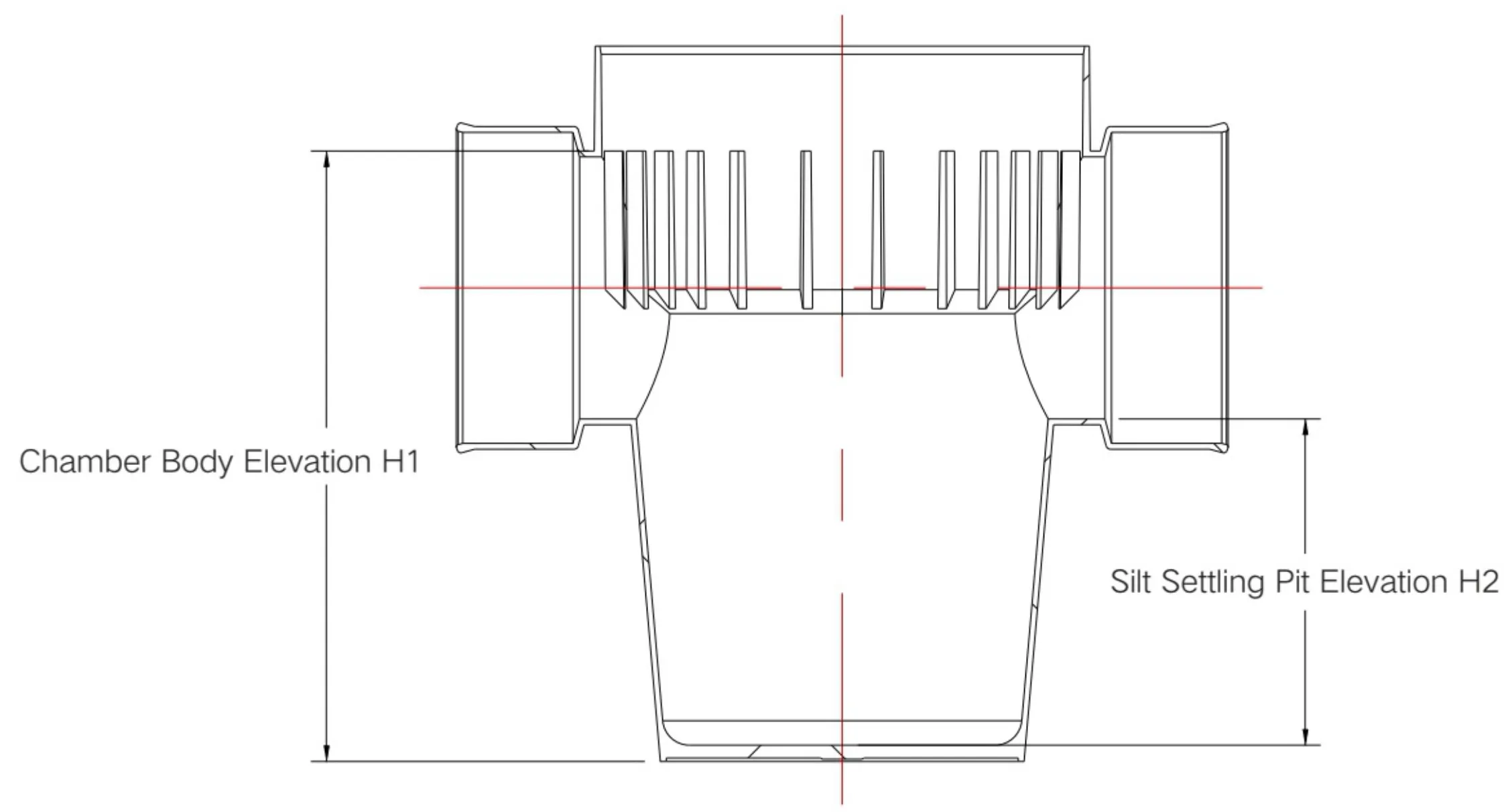
IX. Elevation of Inspection Chamber
1. Elevation of Silt Settling Chamber Body
Figure 6 Elevation of Silt Settling Chamber Body
| 110B | 150A | 160B | 200A | 200B | 225A | 250A | 250B | 300A | 315B | 400A | 400B | 500A | 500B | 600A | 700A | 800A | 1000A | |
| 200 | 341 | 420 | 420 | 447 | ||||||||||||||
| 315 | 485 | 485 | 511 | 511 | 511 | 590 | 541 | |||||||||||
| 400 | 602 | 565 | 698 | 663 | ||||||||||||||
| 450 | 602 | 565 | 698 | 663 | ||||||||||||||
| 500 | 605 | 705 | 672 | |||||||||||||||
| 600 | 613 | 588 | 702 | 664 | 797 | 729 | 908 | |||||||||||
| 630 | 613 | 588 | 702 | 664 | 797 | 729 | 908 | |||||||||||
| 700 | 618 | 717 | 815 | 926 | ||||||||||||||
| 1000 | 838 | 939 | 1034 | 1149 | 1314 | 1343 | ||||||||||||
| 1200 | 1381 |
| Table13EffectiveElevationH2ofSiltSettlingPit(mm) | ||||||||
| Riser Specifications | 315 | 400 | 450 | 500 | 600 | 700 | 800 | 1000 |
| SiltSettling PitElevation | 300 | 300 | 300 | 300 | 300 | 300 | 300 | 500 |
2. Elevations of Launder Chamber Body, Chamber Cover and Convergent Walling Crib
Figure 7 Elevation of Launcher Chamber body

| Riser Specifications | 200 | 315 | 400 | 450 | 500 | 600 | 630 | 700 | 800 | 1000 |
| ChamberCover ElevationH3 | 25 | 32 | 32 | 32 | 40 | 40 | 40 | 40 | 40 | 50 |
| 110B | 150A | 160B | 200A | 200B | 225A | 250A | 250B | 300A | 315B | 400A | 400B | 500A | 500B | 600A | 700A | 800A | 1000A | |
| 200 | 173 | 176 | ||||||||||||||||
| 315 | 180 | 178 | 227 | 210 | 265 | 511 | 265 | 345 | 320 | |||||||||
| 400 | 253 | 213 | 265 | 262 | 345 | 320 | 460 | 405 | ||||||||||
| 450 | 253 | 219 | 265 | 262 | 345 | 320 | 460 | 405 | ||||||||||
| 500 | 219 | 345 | 465 | 405 | ||||||||||||||
| 600 | 345 | 320 | 465 | 405 | 566 | 484 | 665 | |||||||||||
| 630 | 345 | 320 | 465 | 405 | 566 | 484 | 665 | |||||||||||
| 700 | 345 | 475 | 571 | 685 | ||||||||||||||
| 800 | 355 | 480 | 609 | 690 | 957 | |||||||||||||
| 1000 | 355 | 480 | 609 | 690 | 795 | 957 | ||||||||||||
| 1200 | 355 | 480 | 609 | 690 | 795 | 978 | 1095 |
| ShaftRiser Specifications | 1000-700 Convergent Walling Crib (Spigot) | 1000-700 Convergent Walling Crib (Socket) | 1200-700 Convergent Walling Crib (Socket) | 1200-700 Convergent Walling Crib (Socket) | 1000-800 Convergent Walling Crib (Socket) | 1000-800 Convergent Walling Crib (Socket) | 1500-1000 Convergent Walling Crib (Socket) |
| ConvergentCone ElevationH5 | 283 | 285 | 484 | 380 | 218 | 168 | 316 |
X. Installation of Accessories
1. Installation Instructions for Gutty Inlet
(1) After the subgrade is completed and the lawn ground is leveled off, conduct the excavation of the trenches for gutter inlets and rainwaterbranchpipes;
(2) According to the elevation of the gutter inlets and the slope of the rainwater branch pipes, open holes in the casing (riser) pipe of the rainwater inspection chamber, and install the movable joints of the branch pipes;
(3) After the movable joints of the branch pipes are installed and connected,therainwater branch pipes should be connected and laid,and the ends of the branch pipes shallbe sealed temporarily;
(4) When installing the road curbstones, excavate the foundation pit for the gutter inlet and lay the gutty inlet in place. After connecting the branch pipes,fill with medium and fine sand for compaction and fixation.

2. Installation Instructions for Outlet Pipe
2.1 Installation of Movable Joints of BranchPipes
(1) Determine the opening position according to the design elevation;
(2) Open the hole with the hole tapper;
(3) Insert the main body, L-shaped sealing ring and lock block (in that order), and tighten the nut;
(4) Place the foundation of the outlet pipe at the required elevation;
(5) Connect the outlet pipe (the pipe end should be chamfered, fitted with seal ring and applied with the lubricant) without adverse slope.
2.2 Installation of Riser with Opening
(1)Select the length of the firstsection of theriser according to the required elevation;
(2) Install the first section of the riser;
(3) Installthe riser with the opening, and temporarily plug the branch pipe;
(4) Select the length of the second section of the riser according to the required elevation;
(5) Installthesecondsectionof the riser;
(6) Place the foundation of the outlet pipe (inlet pipe) at the required elevation;
(7) Connect the outletpipe(thepipe end should be chamfered,fitted withseal ring and applied with the lubricant)without.adverse slope.
2.3Connection of OutletPipetoChamberBody
(1) Adjust the slope of the outlet pipe according to the required elevation of the outlet pipe and the chamber body;
(2) Connect the outlet pipe (the pipe end should chamfered, fitted with seal ring and applied with the lubricant) without adverse slope;
(3) When the diameter of the outlet pipe is different from that of the branch pipe socket on the chamber body,the chamber body can be placed in through the reducing joint as a transition section;
(4) When there are multiple outlet pipes, it is recommended to connect them to the chamber body through a converging reducing joint as transition, or through PvC drain pipe fittings.
3. Installation Instructions for Saddle Joint
3.1Specifications of Matched HoleTapperforSaddleJoint I
| Table 17Specifications of Matched HoleTapperI forSaddleJoint | |||||
| No. | Specifications of Saddle Joint I | Specifications of Matched Hole Tapper I | No. | Specifications of Saddle Joint I | Specifications of Matched HoleTapperl |
| 1 | P134-315x150A | P150-160B | 19 | P134-400/450×160B | P150-160B |
| 2 | P134-400/450×200A | P150-200A | 20 | P134-400/450×200B | P150-200B |
| 3 | P134-400/450×225A | P150-225A | 21 | P134-400/450×250B | P150-250B |
| 4 | P134-500×200A | P150-200A | 22 | P134-500x110B | P150-110B |
| 5 | P134-500x225A | P150-225A | 23 | P134-500×160B | P150-160B |
| 6 | P134-500x300A | P150-300A | 24 | P134-500×200B | P150-200B |
| 7 | P134-600/630×200A | P150-200A | 25 | P134-500×250B | P150-250B |
| 8 | P134-700×200A | P150-200A | 26 | P134-500x315B | P150-315B |
| 9 | P134-700×225A | P150-225A | 27 | P134-600/630x110B | P150-110B |
| 10 | P134-700x300A | P150-300A | 28 | P134-600/630x160B | P150-160B |
| 11 | P134-200x50B | P150-50B | 29 | P134-600/630×200B | P150-200B |
| 12 | P134-200x75B | P150-75B | 30 | P134-600/630×250B | P150-250B |
| 13 | P134-200x110B | P150-110B | 31 | P134-700x110B | P150-110B |
| 14 | P134-315x75B | P150-75B | 32 | P134-700x160B | P150-160B |
| 15 | P134-315x110B | P150-110B | 33 | P134-700×200B | P150-200B |
| 16 | P134-315×160B | P150-160B | 34 | P134-700×250B | P150-250B |
| 17 | P134-315x200B | P150-200B | 35 | P134-700x315B | P150-315B |
| 18 | P134-400/450×110B | P150-110B | |||

Xl. Construction Instructions for Plastic Inspection Chamber
1. Transportation
(1) The plastic inspection chamber should be handled with great care, and please avoid rolling, dragging or throwing;
(2) When it is hoisted by mechanical equipment, only non-metal ropes(orbelts)should be used;
(3) During transportation, it is advised to place the plastic inspection chamber vertically, and use non-metal ropes (or belts) to bind and fix it in place.Appropriate sun protection measures should be applied.
2. Storage of Inspection Chamber
(1) It should be stored in a well-ventilated place away from heat sources;
(2) When it is stored temporarily in the open air, appropriate sun protection measures should be taken;
(3) When it is placed horizontally, horizontal supports should be provided, with measures taken to prevent the deformation of the socket.
Inspection chambers should not be piled on top of each other;
(4)It must not bestored togetherwith oils or chemicals;
(5) There should be appropriate fire fighting facilities or other fire fighting measures in the warehouse;
(6)Plastic inspection chamber should not be stored for a long time.
3. Preparations Before Construction
(1) Before the installtion of the plastic inspection chamber, the technical disclosure should be conducted concurrently with the completion of the drain pipeline project;
(2) For projects that require bearing rings for road surfaces with load-bearing requirements, the construction party should be informed in advance to customize the bearing rings based on the cement seting period (usually 7-15 days);
(3) Arrive at the construction site in advance to check the construction environment before delivery, communicate with the construction party,and propose a reasonable construction plan.After the plan is determined, construction tools should be prepared on the constructionsiteinadvance; Commonly used construction tools include: gas cylinders, flame guns, steel brushes, rags, gloves, rain shoes, safety helmets, portable cutting machines (for cutting risers), hand-held hole tappers, electric drills (for driling holes on risers),lubricants (for lubrication of riser pipe during connection), pipe tensioner (for connection to riser pipes), etc.
4. Technical Guidelines for Construction
| No. RequiredSteps | TableTg | ||
| TechnologyDescriptionDuring theConstructionProcess Diagram OperatingKeyPoints | |||
| TrenchExcavation | 1)Theexcavation of thefoundationpit forthe chamberbody should be carried out afterthefoundationquality of the drainpipe and theslope of thepipetrench areinspected and accepted.Themain axisof the chamber body should be consistent with that of thepipe. 2)The excavationof thefoundationpit for the silt settling inspectionchamber should be carried out according to the size of thesilt settlingpit,and a 100mm layer of medium-coarsesand should bepaved asa cushion.If the pipediameteris greaterthan60omm,the concretefoundationshould be | ||
| 2 | poured around the silt settling pit. 3)Theexcavationof thefoundationpitforthegutterinletshouldbe conductedwithbackfillingcarriedouttoacertainextentbeforefurther excavation(after the subgrade constructioniscomplete). 1) In case of sand, rock,and sand gravel foundations, a 1oomm layer of | ||
| Treatment of Foundation Pit | 2) In case of soft soil foundation, the pit can be filled with a 150mm layer of crushed stone or gravel (with particle size:5 to 40mm) as a ballast layer.After theballast layeris tamped,a 50mm layerof medium-coarse sand can be applied as a cushion; 3)Incase of collapsible loess foundation,after the original soilof the foundation pit is tamped, a 100 to 150mm layer of lime-soil mixture (with a lime-soil ratio of 3:7) should be laid and tamped as a cushion, after which the 1oomm layer ofmedium-coarse sand can be laid as a | ||
| 3 | Installation of ChamberBody | cushion. 1)Before placing the chamberbodyinto thepit,check the numbers and specificationsofthecomponentsand thediameteroftheconnecting pipes;measure and record any deformation of the cross-section of the upper socket; 2)Thechamberbodyshould behoisted bymanual operationor mechanical equipment into the pit, with non-metal ropes (orbelts) used during hoisting; 3)After placing the chamber body in the pit,level and adjust the center, themain axis,and thebottom elevation of the chamberbody,as well as the chamber bodyitself byusing temporary cushion blocks.After all theseindicatorsmeet thedesignrequirements,stabilizingmeasures sand is filled in, and the cushion blocks are removed; 4)During the installation of the chamber body, the pit cushion should not be disturbed. If the pit cushion is damaged, effective remedial measures should be taken. | |
| No. | Required Steps | TechnologyDescriptionDuring the ConstructionProcess | |
| Diagram | OperatingKeyPoints | ||
| 5 | Connection Between ChamberBody and Pipe | Upstream Installation Direction For thepipereduction direction:horizontal connection of pipe climax for inflow, and horizontal connection of pipe bottom for discharge. Example for the horizontal connection of pipe climax for inflow: Horizontal Connection of Pipe Bottom | 1) Installation steps: body -pipe; b.Determine the centerposition of the chamber on the axis of the pipefoundation; conduct theexcavation of the foundation according to thesize of the chamberbody and lay the cushion; adjust the elevation of thefoundation pit at thebottom of the chamber. 2)The connectionbetween thechamberbody interface and the pipe shall meet the following requirements: a.The connection method of the interface shallbe consistent with that of the pipe; b.In case of the connectionbetween the chamber body interface and the reducing pipe, a reducing joint should be used. Connection principles:horizontal connection of pipe climax for inflow, and horizontal connection of pipe bottom for discharge. c.When the size of the chamberbodyinterface does not match the size of the pipe,the chamber body and the pipe shall be connected through a transition joint and thenreinforced with a thermal shrinkablesleeve; d.When connecting the chamber body with other pipelines, |
| Riser Installation | Horizontal Connection of Pipe Climax plugged. to the horizontal plane. | suitable connection methods canbe used. 1)The connectionbetween theriser and the chamberbody must be installed immediately after the chamberbody is installed; 2)Determine thelengthof theriser according tothe design groundelevationonthedrawing;if theelevationof theground orroad surface is difficult to determine,a suitable margin of riserlength canbereserved; 3) Before making the connection, the chamber body should be fixed inplace;therisershouldbeconnected to thesocketof the chamberbodywitharubbersealringorthermalshrinkable sleeve; 4)Whenconnecting theriser to thechamberbodybyusinga rubberseal ring inabell-and-spigot joint, therisershould be keptvertical.It isnotpermissibletouseheavy objectsfor striking. Instead, special tightening tools should be used; 5)After the riser is installed, the upper end should be temporarily 6)After installation,check to ensure that the riser is perpendicular | |
| No. | Required Steps | TechnologyDescriptionDuring the ConstructionProcess | |
| Diagram | OperatingKeyPoints | ||
| 6 | Closed WaterTest | 注 水 | A closed water test shouldbe carried out after the installation and acceptanceof thepipe and theinspectionchamber;theclosed watertest ontheinspection chambershouldbecarried out at the same time as the closed water test of the pipe system;the method used forthetwotestsshould bethe same. |
| 7 | Backfilling | 井 天 请 | 1)Backfilling shouldbecarriedout after the drainpipe and the inspectionchamberhavepassedacceptanceinspection; 2)Beforebackfilling,theinspectionchambercanbetemporarily fixed by using wooden sticks,sand bags and other measures; thereshould be no accumulated waterin thechamberpit; 3)Backfilling of theinspection chamber and pipe should be carriedouttogether.Withintherangefromthebottomof the chamberbody to 0.5m above the topof the drainpipe,backfill materialssuchas crushedstone andmedium-coarsesand shouldbeused,with the compactiondegreein linewith the designrequirements; 4)Backfilling must not use materials such as silt,garbage and frozensoil,and should not containstones and bricks larger than50 mm,orotherhard objects; 5)Thebackfilling around therisershould be conducted through artificiallayering,symmetricalbackfilling(withlayersof about 50cmeach)andartificial tamping.Thedisplacement andtiting of theinspectionchambershouldbe avoided,andany deformationof therisershouldbecontrolled.Mechanical backfilling isstrictlyprohibited. |
| 8 | Installation of BearingRing and ChamberCover | 6)Inareaswhere thefrost depthof thesoil isgreater thanor equalto1.0m,within a range of not less than100mm around theriserinthefrozensoillayer,high-qualitybackfill materials suchasmedium-coarsesandshouldbeadoptedfor backfilling. (Under roads: sand should be used as backfill. Under farmland: original soil should be used as backfill.) 1)Thebearing capacity of thebearing ring should match thegrade of theroadsurface; 2) The installation of thebearing ring should be conducted simultaneouslywith the construction of theroad surface,and it | |
| is advisabletoprioritize theuseofprecastreinforcedconcrete bearing rings; 3)Theinnerdiameterof thebearingringorificeshouldbegreater thanthe outerdiameter of theriser,with a clearancein the range of 50 to 100mm; 4)A 300mm cushion should be laid under thebearing ring as a foundation.The cushion material canbecrushed stone orC20 concrete; 5)Beforelaying the cushionfor the bearing ring,the antiextrusion ringshouldbeplacedaround theriser,andthewaterseepage measures shouldbe takenfor the gapbetween theriser and the antiextrusion ring; 6)Before hoisting thebearing ring,it should bepositioned onthe cushionwithsmall woodenpilesto ensure that the orifice of thebearing ringis concentric with the riser; 7) During construction of theroad surface,install the cover of the inspectionchamberonthebearingring. | |||
LESSO
LESSOGROUPHOLDINGSLIMITED(STOCK CODE: 2128.HK)
ProductionBase:
Liansu Industrial Estate, Longjiang Town, Shunde District, Foshan City,
GuangdongProvince528318,China
Sales Tel: (86) 757 23379211 Fax: (86) 757 23378980 E-mail: oversea@lesso.com Asia-1: (86) 757-29223015 Africa-1: (86) 757-29226356 Middle East :(86) 757-29226355 Asia-2:(86) 757-29220500 Africa-2: (86) 757-23379211 South America:(86)757-29220501
www.lesso.com

